Tutorials for Drawing Symbols
Electrical Symbols & Electronic Symbols Electrical symbols and electronic circuit symbols are used for drawing schematic diagram. The symbols represent electrical and electronic components. Table of Electrical Symbols See also Electrical components Electrical units Capacitor Resistor Inductor Current Voltage Ohm's law Switch symbols Ground symbols

Architectural Floor Plan Legend Symbols Architecture drawing, Floor
Geometric Dimensioning and Tolerancing Symbols You can either create your own library of GD&T symbols, or use one of AutoCAD's GD&T fonts to insert the symbols as text. The following tables show how to construct the symbols. Any needed height h 2 h h 2 h 60° 2 h Identification letter Datum Feature Symbol Datum Target Symbol Target Point and.

Set of ancient Egyptian symbols Download Free Vectors, Clipart
There are 7 aspects of the GD&T methodology that we will discuss, these include: Views, Dimensions, Tolerances, Symbols, Datum's, Feature Control Frames & Title Blocks. Drawing Views. The first tool in your engineering drawing toolbox is the drawing view. Drawing Views are simply the representation of your component from multiple perspectives.
Civil Engineering Drawing Symbols And Their Meanings at PaintingValley
Because there's not a lot of space on the drawing, engineers use symbols and abbreviations to communicate specifications and dimensions. Symbols are universal and allow anyone to use the engineering drawing to replicate the object regardless of the language they speak. 1. Check numbers in circles for keynotes.

Pin by Team TGM on Drawing Drawings, Art, Symbols
Geometric tolerances are specified using symbols on a drawing. Currently, we have 16 symbols for geometric tolerances, which are categorized according to the tolerance they specify. True Position Theory (Size Value in Rectangular Frame) Classification and Symbols of Geometric Tolerance Characteristics

Insta, Symbols, Drawings, Art, Art Background, Kunst, Sketches
Engineering drawing abbreviations and symbols are used to communicate and detail the characteristics of an engineering drawing. This list includes abbreviations common to the vocabulary of people who work with engineering drawings in the manufacture and inspection of parts and assemblies.
Drawing Landscape Design Symbols Pdf AnaCandelaioull
There are literally hundreds of engineering drawing symbols and they're used in a variety of ways. For example, engineering symbols are used in technical drawings to convey the specific geometry and other details about pieces of equipment or components. To limit errors caused by personal interpretation, engineering drawings and diagrams are.

Pin by Queen BM3 on Personal Pencil & Ink Drawings My drawings
Structural drawings are a series of pages which explain and illustrate the structural design intent of a building or structure. The aim of a good set of structural drawings is to provide the reader with enough information to: Construct that building or structure if you are a contractor

Construction Legend Construction symbols, Architecture symbols
Most new drawings will have an isometric view to guide you. You can use the Bill of Materials to find the components in the drawing in order to understand the role they play in the assembly. Remember that reading an engineering drawing can take a long time, depending on the complexity of the assembly and the experience of the reader.

Mechanical Drawing Symbols
GD&T Flatness is a common symbol that references how flat a surface is regardless of any other datum's or features. It comes in useful if a feature is to be defined on a drawing that needs to be uniformly flat without tightening any other dimensions on the drawing.

Pentacle Drawing at GetDrawings Free download
Engineering Drawing Abbreviations and Symbols. To read an ED, you must first become familiar with the various symbols, abbreviations, and diagram basics. Once you familiarise yourself with these features, you'll be able to trace the lines in a system to understand specific components and the overall function in the case of PFDs and P&IDs or.

ANSI Standard JSTD710 Architectural Drawing Symbols Bedrock Learning
The best way to learn GD&T is from experienced teachers who can break down the material into manageable pieces. Luckily, we know someone. And MachinistGuides.com readers get an exclusive discount on training! Get the Best GD&T Training Available. Blueprint Reading Guides. Check out our full list of machining blueprint symbols to help you figure.

Symbols (By ElenaRaRa) Art, Symbols, Drawings
system, and type of drawing. The drawing number may also contain information such as the sheet number, if the drawing is part of a series, or it may contain the revision level. Drawings are usually filed by their drawing number because the drawing title may be common to several prints or series of prints. Second Area of the Title Block

Blueprint Symbols for Architectural, Electrical, Plumbing & Structural
Figure 1. Equivalent Symbol and Note 1.2 The symbols are presented in two groups for easier use of this section as a reference. General dimensioning symbols are shown first. Some of these symbols are also used in tolerance specifications. The second set of symbols are used for toler-ances.

Symbols 2 Cool symbols, Symbolic art, Symbol design
A simple drawing with GD&T datum symbols. Image Source. GD&T positions every part within a Datum Reference Frame (DRF). Some say the DRF is the most important concept in geometric positioning and tolerancing because it provides the skeleton or frame of reference to which all requirements are connected. For that reason, we want to start early.
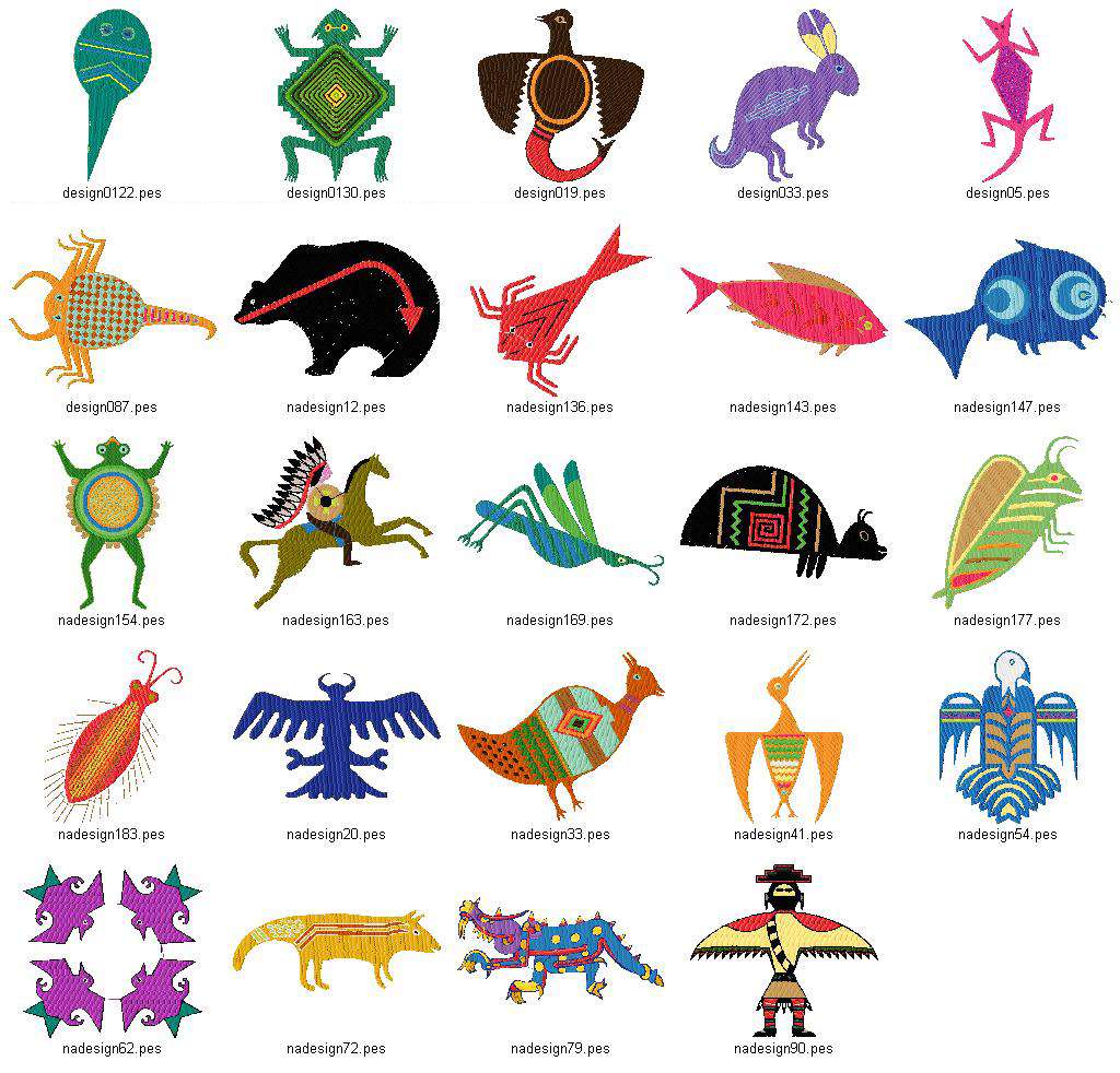
Native American Symbols Drawing at GetDrawings Free download
Engineering Working Drawing Basics is a pdf document that introduces the fundamental principles and practices of engineering drawing. It covers topics such as types of drawings, symbols, dimensions, tolerances, and views. It is a useful resource for students and engineers who want to learn or review the basics of engineering drawing.
